UART on an FPGA - Part 2
Background
As the title suggests this is the second (and final) part of my development process of UART controller module written in SystemVerilog. The first part, which includes a quick explanation of UART along with the development and simulation of the UART receive module can be found here.
After creating the module for the UART transmitter, I combined it with the UART receiver in the top-level module, redirecting any data on the RX line to the TX line. Then the synthesized code was uploaded to the UPduino 3.0 FPGA development board, which is based on the Lattice ICE40 family. A detailed look at how to use the development board with the Lattice Radiant Software here.
The Radiant Software project can be found on github at https://github.com/ChSotiriou/FPGA-UART.
UART Transmitter
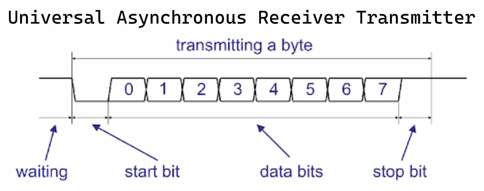
Just like the UART receiver, the transmitter was based on a FSM with the exact same states, IDLE, START_BIT, DATA_BITS, STOP_BIT. But instead of sampling the data line, the line is driven according to the bit that needs to be sent. The parameters given to the module were also very similar, a clock, the signal line, the data, and a transmission trigger signal. The SystemVerilog code for this module is shown below.
module uart_send #(
  parameter baudRate,
  parameter clkFreq
)(
  input logic clk,
  input logic[7:0] data,
  input logic send_trigger,
  output logic signal
);

typedef enum { IDLE, START_BIT, DATA_BITS, STOP_BIT } State;
State uart_send_state = IDLE;

int count = 0;
int clkPulsesPerBit = clkFreq / baudRate;
int bits_send = 0;
logic[7:0] dataToSend;
logic startTransmission = 0;

always @(posedge clk) begin
  count <= count + 1;

  case (uart_send_state)
    IDLE: begin
      signal <= 1;

      if (send_trigger == 1) begin
        uart_send_state <= START_BIT;
        count <= 0;
        dataToSend <= data;
      end
    end
    START_BIT: begin
      signal <= 0;

      if (count == clkPulsesPerBit) begin
        uart_send_state <= DATA_BITS;
        bits_send <= 0;
        count <= 0;
      end
    end
    DATA_BITS: begin
      signal <= dataToSend[bits_send];

      if (count == clkPulsesPerBit) begin
        count <= 0;
        bits_send <= bits_send + 1;

        if (bits_send == 7) begin
          uart_send_state <= STOP_BIT;
        end
      end
    end
    STOP_BIT: begin
      signal <= 1;

      if (count == clkPulsesPerBit) begin
        count <= 0;
        uart_send_state <= IDLE;
      end
    end
    default: uart_send_state <= IDLE;
  endcase
end
endmodule
Simulating and Testing the Transmitter Module
For simulation purposes, a SystemVerilog testbench was created which combined connected the transmitter directly to the previously created UART receiver. The testbench looped around all the possible values of a byte 0x00-0xff and transmitted them, using the newly created UART transmission module, to the UART receiver and cross-referenced the input to the output. If they didn’t match a message was printed out on the screen. The testbench code is shown below.
`timescale 1ns/1ns

module uart_send_tb;

parameter baudRate = 115200;
parameter timePerBit = 1e9 / baudRate;
parameter clkHalfPeriod = 5ns;
parameter clkPerieod = 2*clkHalfPeriod;
parameter clkFreq = 1e9 / (2 * clkHalfPeriod); // ns
parameter fullTransctionDelay = (10e9 / baudRate) + 1000;

logic clk;
logic sendTrigger = 0;
logic signal;
logic[7:0] dataReceived, dataToSend;
logic dataReceivedFlag;
logic dataSendTrigger;

uart_recv #(
  .baudRate(baudRate),
  .clkFreq(clkFreq)
) recv(
  .clk(clk),
  .signal(signal),
  .data(dataReceived),
  .dataReceivedFlag(dataReceivedFlag)
);

uart_send #(
  .baudRate(baudRate),
  .clkFreq(clkFreq)
) send(
  .clk(clk),
  .data(dataToSend),
  .send_trigger(dataSendTrigger),
  .signal(signal)
);

initial begin
  $display("--- Starting Simulation ---");

  for (int i = 0; i <= 8'hff; i++) begin
    dataToSend <= i;
    dataSendTrigger <= 1; #clkPerieod;
    dataSendTrigger <= 0; #clkPerieod;
    #fullTransctionDelay;

    if (dataReceived != i[7:0]) begin
      $error("Received %b, expected %b", dataReceived, i[7:0]);
    end
  end

  $display("--- Ending Simulation ---");
end

always begin
  clk <= 1; #clkHalfPeriod;
  clk <= 0; #clkHalfPeriod;
end

endmodule
Combining Everything Together
Finally, the receiver and transmitter were combined together in the top-level module. The TX line was connected to the UART transmitter, the RX line to the receiver, the received data vector was connected to the send data vector and thedataReceivedFlag was connected to the send trigger signal. To accomplish this, an always_comb block was used. For debugging purposes, the red component of the onboard RGB LED was connected directly to the RX line and the green to the TX line.
After writing the SystemVerilog code the design was synthesized, pins were assigned to the top-level module, and the generated file was flashed onto the board. As mentioned in the introduction of the post more details about this process can be found here.
The function of the complete project is shown in the image below.

module main (
	output logic tx,
	input logic rx,
	input logic clk,
	output logic led_red,
	output logic led_green
);

parameter clkFreq = 12e6;
parameter baudRate = 115200;

logic[7:0] receivedData, sentData;
logic dataReceivedFlag;
logic dataSendFlag = 0;

uart_recv #(
	.baudRate(baudRate),
	.clkFreq(clkFreq)
) recv(
	.clk(clk),
	.signal(rx),
	.data(receivedData),
	.dataReceivedFlag(dataReceivedFlag)
);

uart_send #(
	.baudRate(baudRate),
	.clkFreq(clkFreq)
) send(
	.clk(clk),
	.data(sentData),
	.send_trigger(dataSendFlag),
	.signal(tx)
);

always_comb begin
	led_red = rx;
	led_green = tx;

	dataSendFlag = dataReceivedFlag;
	sentData = receivedData;
end
endmodule
Conclusion
This small journey was very exciting. I learned a lot about SystemVerilog. I believe my initial goal for this project was met. That was to better understand the Verilog / SystemVerilog HDLs. I know that UART projects on FPGAs are everywhere now, so for the future I’m looking to dive into more communication protocols, like I2C, SPI, CAN etc.