UPduino 3.0 Getting Started
Introduction
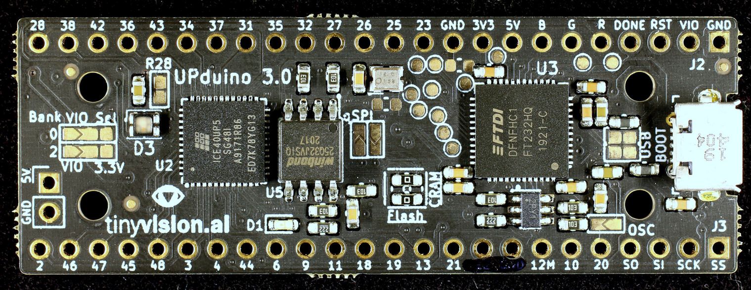
The UPduino 3.0 is an open-source FPGA project, that with its ease of use, is a great way to start your journey in the FPGA world. It is based on the Lattice UltraPlus ICE40UP5K FPGA, with 5.3K LUTs, 1Mb SPRAM, 120Kb DPRAM, and 8 Multipliers. The board also contains an RGB LED, an SPI Flash for programming the FPGA, and many more.
This will not be a guide on HDL languages nor will it be a guide for the Lattice Radiant software package. It will only go through the process of programming the FPGA successfully.
Before starting, I connected the external oscillator to the FPGA with the OSC jumper, which is located on the bottom right of the board as shown in the image above. This was done to provide stability in the FPGA’s timings.
Required Software
This guide will showcase the process of programming the FPGA device with the Lattice Radiant software on Windows 10, as there are a lot of guides on programming the device with open-source toolchains like the APIO project. For the process the following software is needed:
- Lattice Radiant (with free license)
- libusbK FTDI driver (this is the one that seemed to have worked for me)
Lattice Radiant
After the installation of the aforementioned software, we will create a new project and attempt to program it into the SPI flash.
Creating a Project
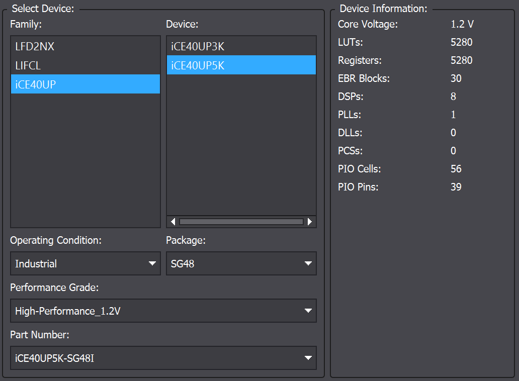
On the welcome screen click on the New Project icon and follow the instructions on creating a new project. When asked to add sources just continue without adding anything. Next, you will be prompted to chose the FPGA device. There chose the ICE40UP family and the ICE40UP5K device. Below that pick the SG48 package. At the bottom, it should list the part number as ICE40UP5K-SG48I.
Writing the HDL Code
Following the project creation go to File > New > File and pick a VHDL file. The RGB LED, which will be used is connected on pins 41, 39, 40 respectively. The code showcased here blinks the LED with white light in a frequency set by generic BLINK_FREQ. Place the code in the VHDL file you just created and Synthesize the Design.
library ieee;
use ieee.std_logic_1164.all;
use ieee.numeric_std.all;

entity blink is
    generic (
        CLK_FREQ : integer := 12e6;
		BLINK_FREQ : integer := 10 -- Blink frequency in Hz
    );
    port (
        clk : in std_logic;
        led_r : out std_logic := '1';
        led_g : out std_logic := '1';
        led_b : out std_logic := '1'
    );
end blink;

architecture rtl of blink is
	signal count : integer := 0;
	signal led_state : std_logic := '1';
begin


    BLINK_PROC : process(clk)
    begin
        if rising_edge(clk) then
            if count = CLK_FREQ / (2 * BLINK_FREQ) then
				count <= 0;
				led_state <= not led_state;
				led_r <= led_state;
				led_g <= led_state;
				led_b <= led_state;
            else
                count <= count + 1;
            end if;
        end if;
    end process;

end architecture;
Pin Assignment
Go to the Device Constraint Editor (Tools > Device Constraint Editor), and assign:
- led_red -> 41
- led_green -> 39
- led_blue -> 40
- clk -> 20
The Device Constraint Editor windows should look like the picture below. Then save the pin configuration in the project folder and close the Device Constraint Editor.

FPGA Programming
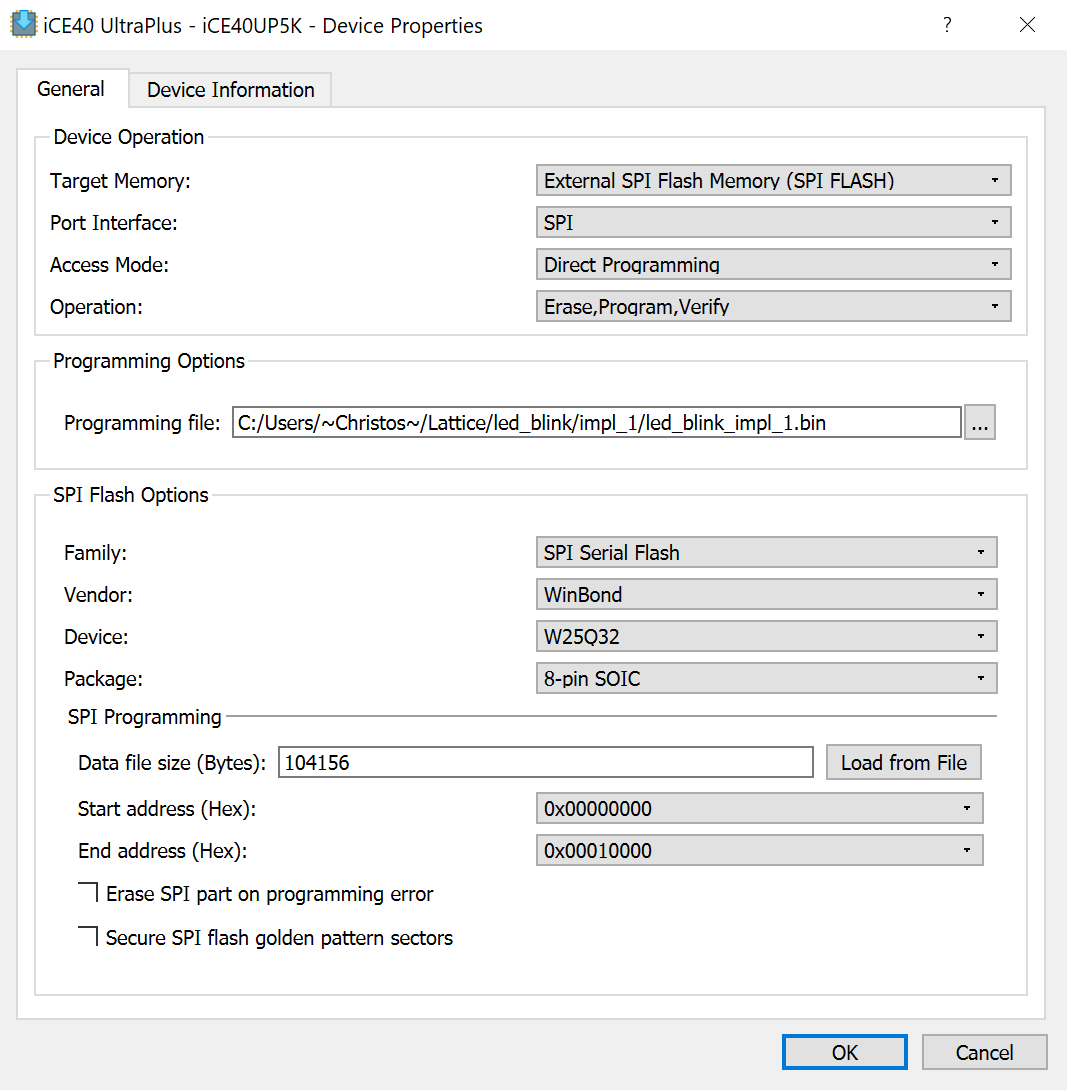
This is the step I got stuck at when I was first trying to upload my code. First, click on Export Files to create the binary file that will be uploaded to the flash. Then open up the Programmer (Tools > Programmer). When the new window opens up make sure that the device family is set to ICE40 UltraPlus and the device is set to ICE40UP5K. Then right-click on the entry in the table and press Device Properties. Here we have to setup the programmer to upload the binary to the external flash memory.
From the first drop-down, target memory, choose External SPI Flash Memory. Under the SPI Flash Options, for vendor pick WinBond, and for the device pick W25Q32 in the 8-pin SOIC package. The windows should look like the image below.
After the setup is complete program the device (Run > Program Device). Now the UPduino 3.0 Board should be blinking with a bright white light.