Maze Solving - Micromouse Robot
Objective
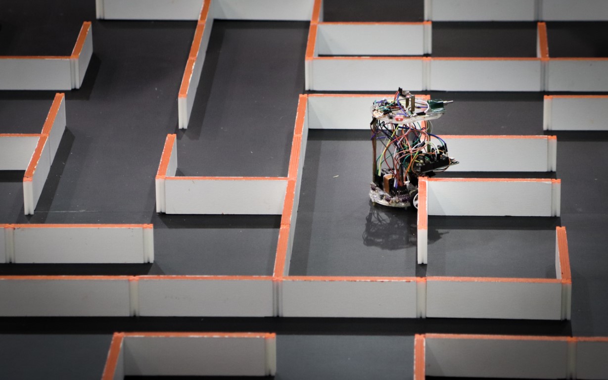
The objective was to built a small and agile maze solving robot that is able to navigate in any randomly generated maze and reach the finish line (the center of the maze). The robot was meant to compete in the first Robotex Cyprus competition in 2017.
Development Timeline
Version 1
For the first version of the project, I chose to put most of my efforts on the maze solving algorithm working perfectly. The algorithm used was a stack based flood fill algorithm.
Putting that much effort in the software meant that the hardware lacked behind. Some notable hardware parts of this first generation include the custom optical encoders made out of tape on the wheels and an off the shelf IR sensor.

Components Used
- 2x 6V DC Motors
- L298N Dual Motor Driver Module
- 9V Battery for power
- Arduino UNO
- 3 Ultrasonic Distance Sensors
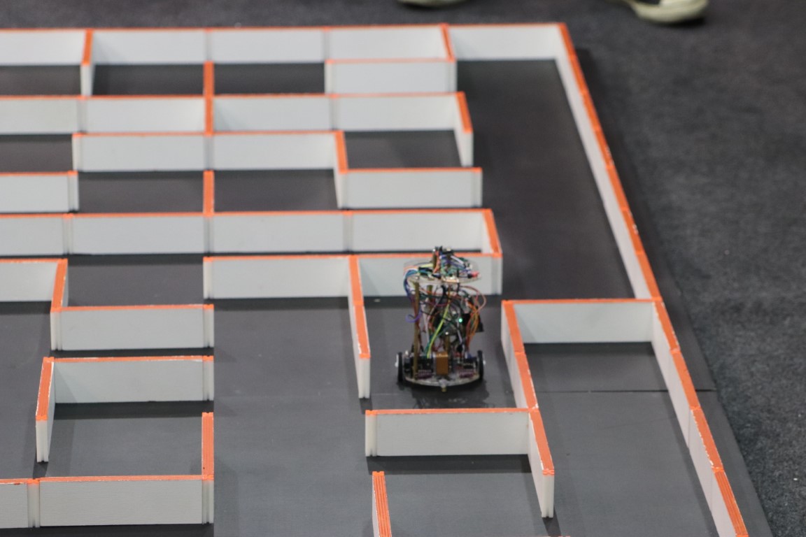
Version 2 (“The Tower”)
This version was a big upgrade compared to the last. Since the last one was focused on perfecting the maze solving software; this was used to add many features to the hardware enabling the robot to move fast and accurately in the maze.
All the parts of the robot where upgraded.
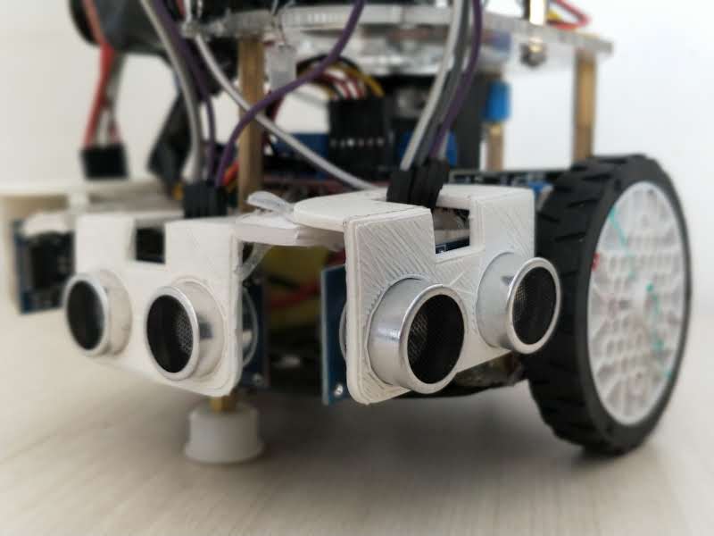
1. The ultrasonic sensors where replaced with 4 VL53L0X time of flight optical distance sensors
- 2 of them where place in the front to enable the robot to align itself parallel to the wall at any point in the maze, increasing its reliability.
- The other two where place on the left and right of the robot
2. The Arduino UNO was replaced with a Cortex M0 based, SAMD21 microcontroller, which was much more powerful.
3. An MPU6050 inertial measurement unit (IMU) was added to the top of the robot to enable it to make accurate and reliable turns.
4. The motor controller was replaced with a TB6612FNG based module.
5. The motors where replaced with micro metal gear motors with quadrature encoders.
- The encoders helped with movement accuracy.
- There was no reliance on time.
- Removed problems when the battery lost charge.
Version 3
The third and final version was made to compact down on the previous one. This process started by the transfer of the version 2 design onto a perforated board. Following the identification of the problems in that design, PCBs where designed and manufactured. The PCB made the robot a lot easier to assemble and debug. From this point on the 9V battery was replaced with a two cell Lithium Polymer (LiPo) battery. There where two versions of the PCB manufactured.
- The first one was a copy of the perforated board version.
- In the second and final robot design:
- the wheels where moved to be inside the robots PCB, making sure the wheels don’t accidentally get stuck on the walls.
- A Bluetooth Low Energy (BLE) module was added to the robot to give wireless control of settings such as speed and calibration.
- Six VL53L0X time of flight sensors where used instead of four.
- A small I2C OLED Display was added to basic configuration

For the above picture, in order from furthest to closest
- Version 2 Robot (“The Tower”)
- Version 3 on perforated board
- Version 3 PCB 1
Below the final version of the robot is shown.
